
Rotary Kiln Incinerator Systems and Requirements for Refractory Materials. A rotary kiln incineration system typically consists of a rotary kiln, a secondary combustion chamber, a waste heat boiler, a quench tower, an acid removal tower, and a dust removal system. Following pretreatment, various types of hazardous waste are introduced into the combustion system via different feeding mechanisms. Driven by gravity and the continuous rotation of the kiln, the materials tumble and come into full contact with combustion air, thereby completing the processes of drying, gasification, and combustion; finally, the residual solids are quenched into slag.
Based on the relative flow directions of flue gas and materials within the incinerator—or, alternatively, the positioning of the rotary kiln’s heat source (burner)—rotary kiln incinerators are classified into two types: counter-current and co-current. When the burner heat source is located at the feed end of the rotary kiln, resulting in the materials and flue gas flowing in the same direction, the system is termed “co-current.” The design of a co-current rotary kiln incinerator is well-suited for material feeding and pretreatment operations; furthermore, it allows for extended flue gas residence times, making it a widely adopted configuration in hazardous waste incineration systems.
The hazardous waste processed by rotary kiln incinerators primarily comprises chemical substances containing chlorine (Cl), sulfur (S), phosphorus (P), halogens, inorganic salts, fluorides, and similar compounds; concurrently, the system also processes certain waste gases and wastewaters. Consequently, the characteristics of the input materials are highly complex. Kiln temperatures typically hover around 1050°C, with specific high-temperature zones reaching levels exceeding 1350°C. Given the complex chemical reactions occurring during processing, the refractory materials lining the kiln are subjected to severe erosive and abrasive wear. Moreover, materials originating from different regions and sources exhibit significant variations in their physical properties, calorific values, and chemical compositions. Therefore, the refractory materials utilized in these systems must possess the following attributes:
- 1) High mechanical strength and excellent abrasion resistance, enabling them to withstand wear caused by solid materials—particularly large iron fragments.
- 2) Excellent volume stability and corrosion resistance, enabling them to withstand chemical attack by acidic substances present within the furnace environment.
- 3) Excellent thermal shock resistance, enabling them to withstand thermal stress damage resulting from fluctuations in the calorific value of the waste stream and corresponding variations in furnace temperature.
- 4) Excellent high-temperature erosion resistance, enabling them to withstand chemical erosion caused by high-salt materials—specifically, molten slags containing fluorides.
Current Status of Refractory Lining Design for Hazardous Waste Rotary Kilns
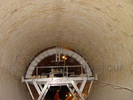
The rotary kiln shell constitutes the most critical component of a rotary kiln incinerator. Due to its high-temperature, dynamic operating environment, it imposes stringent requirements on the lining structure, material selection, and masonry techniques. To ensure stable operation, measures must be taken to prevent issues such as refractory brick detachment or shifting. Depending on plant design specifications and energy conservation requirements, various lining schemes—including single-layer brick, double-layer brick, composite brick, and monolithic castable structures—may be selected. Based on the specific processing temperatures and types of hazardous waste involved, the working layer refractory bricks typically consist of high-alumina, corundum-mullite, or chrome-zircon corundum materials. The total lining thickness is customized according to operational needs, generally ranging from 200 mm to 350 mm.
The thermal conductivity of the refractory materials used for the lining typically falls within the range of 1.7 to 2.0 W·m⁻¹·K⁻¹, or even higher. When a single-layer structure is employed, the temperature of the kiln’s outer shell can eventually exceed 300°C; however, this structure offers excellent overall stability and is well-suited for outdoor installations. Conversely, indoor projects frequently utilize a double-layer structure comprising both insulating bricks and refractory bricks, a configuration that delivers superior energy-saving performance. Nevertheless, this approach results in a thinner working layer of refractory bricks, making them more susceptible to detachment or falling out. Composite bricks feature a working layer composed of corundum-mullite or chrome-corundum materials, backed by an insulating layer made of high-alumina or clay-based materials. However, because the working and insulating layers possess differing coefficients of thermal expansion and sintering shrinkage rates, the efficiency of the brick-forming process and the overall product yield tend to be lower. Furthermore, some projects adopt a monolithic castable structure; this approach not only resolves the issues associated with brick detachment in double-layer systems and the manufacturing complexity of composite bricks, but also allows for the precise adjustment of the insulating layer’s thermal conductivity to effectively control the temperature of the kiln shell’s outer surface. However, this method entails longer construction periods and extended kiln drying (bake-out) cycles.
Refractory Lining Design for Rotary Kiln Hazardous Waste Incinerators
1) The Rotary Kiln Body
The most critical component of a rotary kiln incinerator is the rotary kiln body itself. As a dynamically operating piece of equipment, it imposes stringent requirements on the design of its internal refractory lining structure. Foremost, the design must ensure the overall structural stability of the refractory lining during dynamic, high-temperature operation, thereby preventing issues such as brick detachment or slippage. For hazardous waste rotary kiln systems—which typically operate at relatively low rotational speeds (generally below 1 revolution per minute)—various structural configurations may be selected based on plant layout and energy conservation requirements; these include single-layer brick, double-layer brick, composite brick, and monolithic castable linings. The total thickness of the refractory lining in a rotary kiln typically ranges from 250 mm to 300 mm. The material selected for the working layer (the innermost layer of refractory bricks) is generally determined by the specific processing temperature and the type of hazardous waste being treated; common choices include high-alumina, corundum-mullite, and chrome-zircon-corundum refractory materials. When a single-layer structure with a thickness of 230–300 mm is employed—given that the thermal conductivity of most refractory materials exceeds 1.7–2.0 W/(m·K)—the temperature of the kiln’s outer shell in the high-temperature zone may eventually rise above 350°C. However, this configuration offers excellent overall structural stability, making it well-suited for rotary kiln installations located outdoors.
Alternatively, a double-layer structure comprising both insulating bricks and refractory bricks may be adopted. Because insulating bricks possess low thermal conductivity, they effectively reduce the temperature of the kiln shell; this allows the outer shell temperature to be maintained at approximately 220°C or lower, resulting in significant energy savings. However, this configuration imposes higher demands on construction and installation procedures, making it more suitable for indoor installations. It should be noted that insulating bricks used in this context typically require a compressive strength exceeding 20 MPa, and the designed thickness of the insulating layer must not be less than 50 mm.
To achieve both the structural stability of a single-layer brick lining and the reduced outer shell temperatures associated with insulating layers, a “composite brick” design may be utilized. In this configuration, the working face consists of corundum or chrome-corundum bricks, while the backing layer is composed of materials such as alumina hollow spheres, high-alumina, or clay-based refractories, forming an insulating layer approximately 50–70 mm thick. However, the production efficiency of such composite bricks is relatively low. Furthermore, due to the differing coefficients of thermal expansion and sintering shrinkage rates between the working layer and the insulating layer, micro-cracks are prone to forming at the interface between the two materials, resulting in a relatively high product rejection rate. In light of this, a grooved composite brick design can be adopted; while the material of the working layer remains unchanged, grooves are cut into the rear face and filled with thermal insulation materials, such as nanopanels. This type of grooved composite brick design is not only convenient for manufacturing and installation but also effectively reduces the temperature of the kiln shell’s outer wall by approximately 30 to 50°C.
Alternatively, some rotary kilns utilize lightweight castables or fiberboards as insulating layers, paired with a working layer composed of heavy-duty castables (anchored by metal studs) in a double-layer monolithic structure; this configuration allows for effective control over the rotary kiln’s outer wall temperature. This structure employs metal components to securely bond the refractory materials to the kiln shell, thereby eliminating the risk of refractory bricks detaching. However, the quality of the metal component welding and the proper drying and expulsion of moisture from the castables are critical factors for the success of this design.
By comparison, the refractory brick solution offers greater convenience regarding maintenance and replacement, and is less susceptible to adverse environmental conditions or human error. Currently, rotary kilns in newly constructed projects are almost exclusively designed for outdoor installation; given the increasing demands for production capacity and environmental compliance, a single-layer refractory structure generally offers superior stability. For high-temperature zones within the kiln, the grooved composite brick approach can be considered as a means to effectively lower the outer wall temperature. Furthermore, from a corrosion-prevention perspective, maintaining the kiln shell’s outer wall temperature within the range of 160°C to 320°C is considered a prudent and reasonable practice.
2) Secondary Combustion Chamber
The primary function of the secondary combustion chamber is to subject flue gas to a secondary combustion process, facilitating the incineration and decomposition of combustible components, fly ash particles, dioxins, and similar substances. This process involves the simultaneous occurrence of physical and chemical reactions, which are highly intense. Typically, the secondary combustion chamber comprises refractory materials, thermal insulation materials, and thermal barrier materials. Specifically, refractory materials refer to the working layer, consisting of heavy-weight castables, plastic refractories, or refractory bricks. Thermal insulation materials include insulating castables and insulating bricks, while thermal barrier materials encompass calcium silicate boards, ceramic fiber boards, and nano-boards. Currently, the design of the secondary combustion chamber lining primarily follows three approaches:
- (1) Scheme 1: Comprising refractory materials, thermal insulation materials, and thermal barrier materials. In this three-layer structural design—taking a total thickness of 450 mm as an example—the temperature of the outer wall remains between 80°C and 90°C.
- (2) Scheme 2: Comprising refractory materials and thermal insulation materials. This structural configuration results in a higher outer wall temperature; taking a total thickness of 305 mm as an example, the temperature reaches between 150°C and 180°C.
- (3) Scheme 3: Comprising refractory materials and thermal barrier materials. This scheme represents an intermediate option between the first two; taking a total thickness of 270 mm as an example, the outer wall temperature ranges from approximately 110°C to 140°C.
Generally, the temperature within the secondary combustion chamber ranges from 1100°C to 1200°C, while localized temperatures in the vicinity of the burners may even exceed 1300°C. Therefore, selecting corundum-mullite materials for the working layer is sufficient to meet operational requirements; however, for the working layer in the burner zone, the use of corundum-based or chrome-corundum materials is recommended. Comparatively speaking, the three-layer structural design (Scheme 1) offers superior stability, significantly reducing the likelihood of unscheduled shutdowns for maintenance—which might otherwise be necessitated by high-temperature corrosion or thermal deformation of the chamber shell caused by air leakage or flame channeling.
3) Other Sections
In the waste heat boiler section, wear-resistant castables are primarily required for the ash hoppers, headers, top seals, and outlet flues. Specifically, the ash hoppers typically utilize a dual-layer structure consisting of both insulating materials and wear-resistant castables, with a total thickness generally ranging from 200 to 250 mm.
The quench tower employs acid-resistant castables or acid-resistant mortars. In the upper zone—extending approximately 2 meters downward from the top—temperatures are relatively high; therefore, a 25 mm layer of insulating material may be incorporated as a thermal barrier, resulting in a total lining thickness of 100 mm.
Typical Rotary Kiln Hazardous Waste Processes and Refractory Design Optimization
Based on on-site investigations, it has been observed that refractory damage is primarily concentrated within the main body of the rotary kiln. Hazardous waste incineration typically involves several distinct processing methods; accordingly, the following recommendations for design optimization are proposed:
1) Processing Materials with High Moisture Content
When the material entering the kiln has a high moisture content, the refractory lining at the feed end suffers from severe thermal spalling. Refractory materials exhibiting excellent thermal shock resistance—such as mullite-based, corundum-mullite, or corundum-silicon carbide compositions—are well-suited for use in this specific zone.
2) High Volume of Waste Liquid at the Kiln Head / Poor Atomization
Typically, waste liquids are processed at the kiln head using atomizing lances, with the primary incineration zone located within the drying section. If equipment-related issues result in poor atomization, the refractory lining in this zone is prone to spalling and damage. Mullite-based, corundum-mullite, and corundum-silicon carbide materials are equally suitable for this application. During operation, it is advisable to increase the frequency of inspections for the atomization equipment; furthermore, the volume of waste liquid processed should ideally not exceed 30% of the total feed.
3) Processing Large Volumes of Hard Materials (e.g., Iron Sheets/Drums)
Materials such as iron drums possess high hardness; given the relatively slow rotation speed of the kiln, the repeated tumbling of these materials inside the chamber causes severe mechanical abrasion in the feed zone. The selection of corundum-silicon carbide refractories—which feature high mechanical strength and superior abrasion resistance—has proven highly effective in mitigating this issue.
4) Materials with High Content of Low-Melting-Point Salts
When the content of potassium (K) and sodium (Na) salts in the feed material exceeds 5%, the melting point of the mixture drops significantly. This facilitates the formation of high-temperature molten slag, which leads to severe penetration and corrosion of the refractory lining. In instances where such high-temperature slag formation occurs, the use of chrome-zirconia corundum refractories is the most appropriate choice for the high-temperature zone; typically, these materials feature a Cr2O3 content ranging from 3% to 10%.
5) Materials with High Fluorine Content
When the fluorine content in the feed material is relatively high—ranging from 1% to 4%—the fluorine (F) readily reacts with the silicon (Si) present in the refractory lining. This reaction generates gaseous silicon tetrafluoride (SiF4), which disrupts the structural matrix of the lining and leads to rapid corrosion. Consequently, it is imperative to strictly control the impurity levels within the refractory materials, particularly their silica (SiO2) content. The use of chrome-corundum refractories with a Cr2O3 content ranging from 9% to 15% can effectively meet the operational requirements of the rotary kiln under these conditions. Hazardous waste incineration is an emerging field characterized by a wide variety of waste types with highly variable physical properties and calorific values; consequently, the linings for rotary kilns and secondary combustion chambers are designed in diverse configurations to meet specific requirements. As national regulations governing hazardous waste become increasingly stringent, large-scale rotary kiln incineration technology is poised for broader application in waste treatment, thereby presenting new challenges regarding the selection and design of refractory materials for these incinerators. Compared to traditional high-temperature furnaces, researchers in the field of refractory materials must place greater emphasis on the specific characteristics of hazardous waste materials and the unique operational conditions—such as incineration temperatures and flue gas composition—inherent to this process.